The HP DreamColor LP2480zx is a top-of-the-line color-critical monitor that retailed for $3500 and features some really impressive specs, such as a true 10-bit IPS panel, hardware-based calibration, and an RGB LED backlight. Unfortunately, these monitors eventually develop a purple/magenta color cast over the entire screen and calibrating with HP's proprietary solution does not fix the problem. I got my hands on one of these monitors on eBay for around $100 (so around 3% of the retail price) due to the aforementioned purple-tint issue and set out to fix it. Here is my journey.
The tech
The first question on many people's minds is "why bother?" Aside from the enjoyment of solving problems and tinkering with electronics, this monitor boasts some seriously impressive specs even by today's standards, despite being released way back in 2008. The monitor was developed by HP in collaboration with DreamWorks Animation (hence the name) and was used for color-critical work. Here are some of the goodies:
- True 10-bit IPS panel which allows for not 50, not 256, but a whopping 1024 shades of gray and a total of over 1.07 billion colors. The modern-day DreamColor monitors are inferior since they use 8-bit panels with dithering (AFRC).
- RGB LED backlight which allows for adjustments to the white balance of the display without any loss of color resolution and compensation for wear over time (at least in theory... more on this below).
- Extremely wide color gamut which exceeds "wide gamut" Adobe RGB and nearly meets the Digital Cinema P3 gamut. This monitor will display colors that most monitors simply can't.
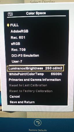
- "DreamColor Engine" which performs hardware-based calibration of the monitor. This is accomplished via matrix multiplier which allows for some rather sophisticated color transformations. Color space presets can be quickly selected via the press of a button and are meant to be programmed in via a proprietary calibration probe and software, ensuring accurate colors throughout the life of the monitor.
- A-TW polarizer which greatly reduces "IPS glow", where colors appear washed out when viewed off-angle. You can clearly see the difference between a monitor with and without it in the picture at the top of this page.
The problem
The monitor uses an LG LM240WU5-SLA1 panel with an RGB backlight. Since LEDs can age at different rates (which causes colors to drift over time), LG thoughtfully included a color sensor and a color processing chip (Avago HDJD-J822) to maintain uniformity of colors. This allows the rest of the monitor's electronics to not worry about backlight drift – in fact, the backlight module accepts absolute Yxy coordinates instead of RGB for colors, which HP's circuitry uses to set brightness and white balance.
Unfortunately, the sensor in these panels goes bad within a few years. The failed sensor measures excessive amounts of green and compensates by turning down the green LEDs. Since there is no way to set individual RGB values for the backlight using the panel's interface, HP's circuitry is unable to compensate for this. The best it can do is utilize the DreamColor engine to calibrate the LCD panel, but after a certain point, there simply isn't enough green light for it to meet the characteristics of the desired color space and calibration fails. The purple color is seen at all times, including the "Scanning inputs" message that displays as soon as the monitor is powered on.
The whole scenario reminds me of a Douglas Adams quote.
The major difference between a thing that might go wrong and a thing that cannot possibly go wrong is that when a thing that cannot possibly go wrong goes wrong it usually turns out to be impossible to get at or repair.
There is no way for monitors using this panel to adjust individual R/G/B values of the backlight, whether via proprietary calibration solution like the DreamColor or manual adjustment like most other monitors, because the panel simply does not provide the appropriate commands to do so. (Even LG's own W2420R has an RGB adjustment limited to requesting Yxy coordinates, which would be inaccurate due to the failed sensor.) The sensor that was intended to maintain the backlight's color uniformity over time ended up making the problem far worse.
Exploring the color management system
I read through the datasheet of the Avago color chip and determined that it used the sensor's inputs to drive PWM outputs to control the actual backlight. The system normally operates in a "closed loop" mode where requests for a particular color are modified based on what the sensor is reading. At the factory, the system is put into "open loop" mode and an external colorimeter is used to measure actual values; this data is stored in the chip and is used for calculations during normal use.
After disassembling the monitor, the first step was to unplug the sensor from the LED driver board. I didn't have very high hopes but I powered on the monitor. For the first time, I saw a pure white background in the "check video cable" message, instead of a purple-tinted one. Success! Unfortunately this was short-lived, since any attempts at adjusting the monitor's settings (or even leaving it alone for a bit) resulted in each backlight color fading to a single channel within a few minutes. Only a complete power-down of the monitor would bring back the brief white backlight.
One possible solution would be to modify the factory calibration data on the chip. Unfortunately this would be a short-term solution since the color sensor would continue to wear out (and this wouldn't work if the sensor aged too far). I also lack the equipment and skills to remove and reinstall a surface-mounted chip in order to send it the necessary I2C commands, and the datasheet isn't clear on how to format the data.
Another possible solution would be to use a variable resistor to compensate for the sensor's output. I did not have success with this (splicing the resistor into the green channel). Due to the system operating in a closed loop, having the resistor even slightly off would result in similarly invalid results.
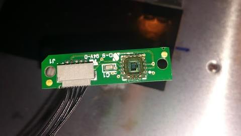
I eventually took the whole panel apart and removed the sensor itself. It was labeled "SD-9 94V-D" on one side and "0831" on the other. Unfortunately I could not find any data online about it, so replacing the sensor itself was out of the question. (And even if I could, it would likely have required factory calibration.)
Directly controlling the backlight with an Arduino
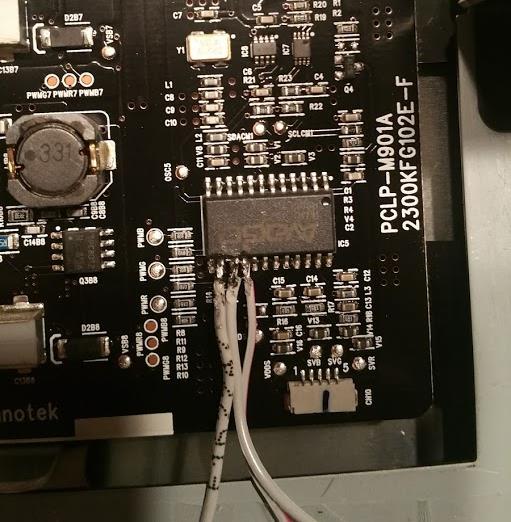
At this point I realized that the only feasible option was to directly control the backlight via PWM, bypassing the Avago color chip entirely. I had an Arduino at my disposal (which allows for several channels of PWM). Lacking any real tools for surface-mount work, I used an Xacto knife and needle-nose pliers to break the PWM output pins off of the chip, and then (after much trial and error) managed to solder 3 wires to the pads underneath it. This was the point of no return.
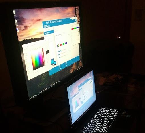
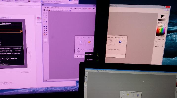
I wrote up a quick sketch to cycle an RGB LED through the full color spectrum and uploaded it to my Arduino. Then I plugged the Arduino into the monitor's USB hub, attached the wires, and turned it on. I was not expecting much, but to my surprise, the monitor powered up successfully and the "Check signal cable" message displayed with a fading rainbow of colors!
The same thing from another angle:
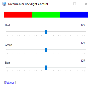
Backlight control software
In order to control the backlight, I created a simple Arduino sketch to hold the 3 PWM pins at a specific value, then listen over serial for new values. I also created a front end application to allow easy control from Windows. To keep things simple, I hard-coded default values (which are applied every time the monitor is powered on) but I could improve the functionality by allowing the Arduino to save those settings.
Finalizing the build
The Arduino fit nicely into an empty space near the cooling fan, although the USB plug was a bit too long. I held it in place with tape.
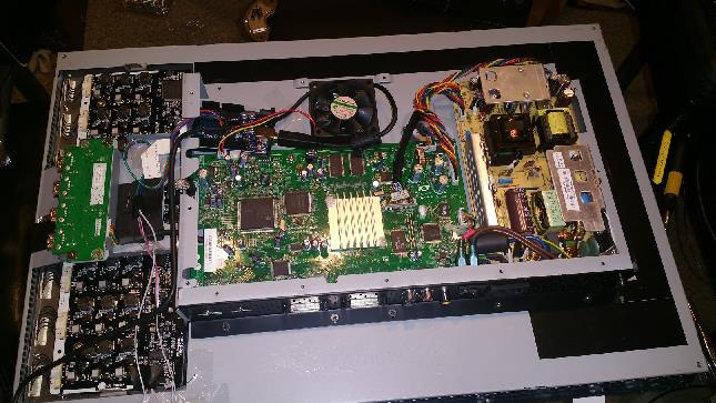
I ran the USB cable through a small hole I made in the outer casing of the monitor and plugged it into the hub on the side. This provides the Arduino with power and allows the computer to communicate with the Arduino through the uplink port.
Limitations
Monitor controls
Since the color chip has been bypassed, the monitor's brightness and white balance controls are no longer functional. The only way to adjust brightness is through the app. The 3D LUT and matrix multiplier are still functional, however, so it should be possible to calibrate the monitor in hardware and use the color profiles. I'm not sure if the official HP Advanced Profiling Solution will still work as I do not own one.
PWM frequency
The Arduino is unable to output a high enough PWM frequency. Thus, the backlight flickers very noticeably unless it's near maximum. Near the lower end of the range, it looks like a strobe light. This is the biggest downside of my solution at this point; perhaps I can find a better microcontroller with a higher PWM frequency.
USB cable
Since the Arduino is powered via USB, and the backlight is now entirely dependent on the Arduino's PWM signal, the USB cable must be connected at all times. This uses up one of the four USB ports on the monitor.
Conclusion
Here is a demonstration of the final product.
If you'd like to attempt the mod yourself or look at my code, you may download it here.
I welcome any suggestions for improvement.
![[XML]](/images/xml.png)
Comments (126)
I have the same issue my LP2480zx. Congratulations for your work.
I want to try your solution.
I'm not samiliar with Arduino but I can solder pretty well, even on those tiny chips.
Could you do a step by step tutorial to perform this repair procedure ?
In particular, identify the points to solder to the Arduino Board.
Regards.
For the Arduino, you don't have to solder anything. Insert the solid wires into the Arduino's output pins 9 (red), 10 (green), and 11 (blue), then upload the sketch linked at the bottom of this page and run the included control software.
Thank you.
Indeed, with the datasheet that is more clear to me.
pin #14 (PWN_B) to arduino output pin #11 (blue)
pin #15 (PWN_G) to arduino output pin #10 (green)
pin #16 (PWN_R) to arduino output pin #9 (red)
To be clear, I have to cut the pins 14, 15 and 16 of the chip and after solder theses three wires to the board underneath.
Is any Arduino board compatible with your code or do I have to purchase a specific one ? Even the cheapest ? :D
Thanks again.
Regards.
Any Arduino board marketed as an "Uno" should work (whether genuine or knockoff).
I ordered an "UNO R3 ATmega328P Development Board With Boot Loader For Arduino UNO F7" for 3$.
I hope it will do the trick and I'll keep you update on my repair. :D
Thanks again.
Regards.
Wiring job done.
I messed up de-soldering one leg of the chip (one pad broke), so I choose to solder the wires on the smd resistors.
Some pictures of my intervention.
http://reho.st/self/56b3f57409c57da960168f19a928428a1bcca59b.jpg
http://reho.st/self/e2347135991ceb06c4f70746f388c8e74aa6f01f.jpg
After taking this photographies, when bending the wire, one of of theses smd resistor unsticked of the board. The one corresponding to the pin #14 (PWN_B). No luck again.
So I decided to solder the blue wire to the pcb board point near marked as "PWNB". I placed a 1k resistor to this point (replacing like this the smd untiscked) and soldering the wire to this resistor. And it worked fine !
I think this could done to all. Solder a 1k resistor on each PCB points marked as "PWNR" ,"PWNG", "PWNB", and wire to the arduino board from theses resistors. It's an easier and safer way because the solder point are much bigger. ;)
The HP DreamColor LP2480zx colours are now fine. Thanks.
I was not able to use your program "Arduino Dreamcolor.exe". When I launch it. Windows tells me that is not a valid application. I surely miss a step.
Do I have to install another program before launching it ?
Thanks for your work, your dedication and your help, Nookkin. ;)
Regards.
HDJD-S822-QR999
RGB Color Sensor
I running on Windows XP 32 bits and I have .Net Framework 4 Extended installed.
Regards,
Sorry, but I do not know how to build a 32 bits release. :/
What software do I have to use ?
Regards.
I have one with the HP Dreamcolor Calibration System tool.
I have a poor colour vision, but even I can see the white point has shifted towards purple. Backlight hours is about 13000. I haven't been able to complete the calibration reliably for many year and been to frustrated to even try most of the time. Nowadays the original v1 puck model calorimeter produces wrong calors because its filters have evidently faded. I am now ordering the v2 model which has sealed filters and hopefully longer life.
I would rather consider replacing the sensor chip than doing my own PWM. This requires removing the old sensor chip with soldering station with heat blower and replacing it with new one, perhaps baking it in soldering oven. Another option is to build a new sensor board. The sensor board has one sensor chip, one capacitor and one connector with 5 pins. Shouldn't be totally impossible and it wouldn't have to be pretty.
Yes, changing the sensor chip shifts factory calibration. One could compensate this by adding an adjustable gain voltage follower for each 3 channels. This would be basically be one quad op amp chip and additional parts. The gains would have to be adjusted to match the original sensor chip sensitivies at the time factory calibration. Mismatching sensitivities would show up as white point being in other position than desired.
Kynix at Hong Kong seems to sell HDJD-S822-QR999 sensors at single chip quantities for about USD 5 each, shipping costs USD 35.
@Gerard If the price is right I'd consider attempting a different repair (the color chip replacement) on a second one.
I used Dispcal from ArgyllCMS to check the white point after calibration and then compensate for the difference between desired and measured white and calculate new coordinates and re-calibrate. Fortunately the HP calibration software allows using custom white coordinates. I had to repeat the calibrate-compensate cycle many times. To get D65 at xy coordinates 313 329, I now use custom values 327 320.
So I don't have immediate need to replace the color sensor. I have nevertheless ordered few sensors from Kynix and I now have SMD rework station. Possibly the change of factory calibration of new sensor chip could be compensated with just using custom coordinates.
I just found out about a (now-discontinued) color sensor chip sold by Sparkfun ( https://www.sparkfun.com/products/retired/10904 ) that uses the HDJD-S822-QR999 color sensor, and I wonder if could be used with the Uno (or as Jarkko mentioned earlier, to build a new sensor board) to approach this issue in a different way...
I have a hot-air rework station but would need a lot of practice with scrap boards until attempting to replace the sensor.
Tried also to get Ookala calibration software (from Sourceforge) working but I does only work the original version of LP2480zx where all traffic went through DDC. Onlu simple commands work now over DDC but table reads and writes do not and crash the monitor. In the newer models there is a proprietary USB-i2c bridge. I have tried to sniff the traffic and but again can only do simple commands.
@quiksilver The sensor itself is on a breakout board as pictured. If you could build an equivalent board and mount the new sensor in its original hole, it should be doable without hot air. Unfortunately I don't know how well it would work if you can't set the factory calibration.
I'm following this guide: http://h22235.www2.hp.com/hpinfo/globalcitizenship/environment/productdata/Countries/_MultiCountry/disassembly_monito_20088216127.pdf
On my monitor, it feels as though the back cover is glued on. Is there a trick to removing the rear cover of the monitor?
See the image below. Stick your pry tool (a putty knife or flat screwdriver works) under the "lip", pointy end towards the front of the monitor (i.e. downwards if the monitor is lying face down).
Plugged the monitor in to test and it works!
Now I just have to summon the patience to put the monitor back together.
For anyone wondering where to get the gels, I ended up purchasing the "Rosco Cinegel Swatchbook" from B&H, and it had more than enough samples to potentially work with.
Thanks to nookkin and everyone else for all the help! Hopefully this monitor will last me a year or two more!
I spent total $300 on this monitor in case you need the reference.
You'll need to remove a metal cover. The sensor is under the white thing with the wires coming out.
At first, I thought taking apart the monitor and performing this particular fix would be simple, but this monitor is one of the most complicated monitor's I've come across (taking it apart, the amount of hardware involved, working with the sensor itself, and putting it back together). At first I thought if this hacked worked well it would be worth getting a few more monitors as backups. Unfortunately, while this monitor is still one of the best monitors i've ever worked with, the price of newer 4k AdobeRGB monitors is coming down, so I don't think it is as economical of an option as I first thought it would be.
In any case, I'm looking forward to potential updates on other users' solutions!
- Remove back and the metal shield screws per usual
- Don't bother removing the mainboard nor the power supply, nor any cables except the one leading to the panel itself in the center of the mainboard and the shielded cable on the left (and disconnect this at the panel side, not the mainboard)
- Remove the USB hub only to get to the ribbon cable for the buttons
The color filter mod was actually rather successful, but I noticed that the white point would need shifting or the display would end up cycling between red and blue in one case. Further, brightness controls were essentially nonexistent. Removing a bit of filter fixed that for me.
My other LP2480ZX also benefited from this mod but still has a haze; I plan to address that with more filter this weekend.
I'm also curious as to how to get internal calibration to work without HP's scarce and questionable i1d2-based calibration solution.
Any ideas? Was I suppose to remove the sensor?
How do I reduce the flicker?
How to I activate the windows RED GREEN BLUE menu?
Ran displaycal successfully and the contrast and saturation looks great.
The problem I am facing right now is that it has become apparent that the white balance is very inconsistent across the screen. Green bands and red leaking. Most notably on the upper half and on the left side, facing the monitor.
Is this the panel failing or another component potentially? Can it be replaced affordably? Is this the end of the road? :(
It will flicker like crazy at lower brightness due to the Arduino's low PWM frequency. I have to keep mine pretty close to full brightness to make it go away.
If you want to use the Windows menu, download the Arduino DreamColor Fix zip file. I added the compiled EXE so you don't have to compile from source.
Do you have a picture of the inconsistent white balance? It's possible that someone calibrated it as far as it could go with the purple -- I would test white balance settings using the "Monitor Going to Sleep" error which is "immune" to the DreamColor calibration. Unfortunately it's probably cheaper to buy a replacement "purple" screen on eBay than to repair the current one.
I’m not at home right now, I will send a picture later today! How do you test with the monitor error? Right now the monitor is set to factory settings. I have both the new and old HP calibrator units and I ran them for calibration with the HP DreamColor Solution software before your Arduino mod. Both calibration units failed, the old school puck made everything red and the new dp1 or w/e it’s called made everything slightly green and the brightness dim. Using your Arduino I basically had to boost the greens a lot and boost the reds and blues a bit too. I can send a screen shot of the white balance measurement on display cal later today too.
Would this purple panel still potentially resolve the white balance inconsistentcy and at what price would one anticipate paying?@nookkin
Another possibility might be to bypass the DreamColor Engine by feeding the monitor an interlaced or YCbCr signal -- either do this digitally in your graphics card's control panel or use the Composite input with only the green (Y) plug connected. You'll know when you receive a "Color Gamut Remapping Disabled" message. See if there is a noticeable change in white balance with constant backlight settings via Arduino.
Can you try calibration with all PWM channels on the Arduino set to 250 (maximum range my Windows app supports)?
I'm confused as to what you want me to do with the OSD menu with transparency set to 0. You want me to put the calibration unit on that and get a white balance measurement?
I was able to bypass the DreamColor Engine by setting the graphics card's control to YCbCr at which point I saw the message "Color Gamut Remapping Disabled". I also set this in Arduino and uploaded it"//Load default values (Experimentally obtained for my own
//monitor, yours will likely be different)
red=250;
green=250;
blue=250;"
Is that what you wanted? I then ran the calibration and I think the white balance is a bit more consistent now. However, I can still see that the upper 1/4 of the screen is ever so slightly red and the bottom 3/4's is ever so slightly green. At a second glance it almost looks more like the bottom 3/4s is just too green and the upper 1/4 is probably about right.
Wondering if you know why when using HDMI as the input I no longer have color space options (ex. REC709). It is locked to "full". Ideas? Hoping to use REC709 in Davinci Resolve!
Cheers,
Erik
Your expertise saved this screen, allowed me to get off the phone with HP and avoid settling for a 6bit panel from Viewsonic! Thank you for your efforts, god bless you man!
you receive a new panel with the stuck pixel or was a refurbished one? The LCD panel has the color sensor?
A friend give me this monitor for free because of the purple issue. He said he can not fix it. I want to give a second chance to this excellent monitor but I do not have any electronics or soldering skills to make this mod with arduino. I think is a better option for me just to replace the LCD panel if that fixes the issue. Can you tell me what happened in your case?
Regars
Earlier, I had used the gel filter mod described in the comments, but this particular monitor (with 38,000 hours!) never seemed to do anything but color-shift until giving up, even after sanding down the color sensor in an attempt to get more light into it.
I'll look into ways to increase the PWM frequency from here to above 610Hz (according to datasheet, the HDJD-J822's PWM output runs at that freq. in a "typical" setup), as well as perhaps making a better program with user-controllable color temperatures/brightness presets that might also work on Linux and Mac OS.
I might probably just end up making manual hardware controls so I don't really have to deal with programs in the first place. I much prefer manual control.
I brought it from here, just in case if you want to know.
https://www.aliexpress.com/wholesale?catId=0&initiative_id=SB_20180316230328&SearchText=LM240WU5-SLA1
For the flickering, maybe a hardware trick can be done like this one :
https://geektimes.ru/post/258098/
I'm using the HP DreamColor as a third screen dedicate to movies. After the Arduino mod, the impossibility to adjust the brightness is my main issue. I wonder if a hardware ajustement like this one can be done to adjust the backlight intensity ?
Regards,
Unic
Keep in mind it's a full-array LED backlight, not just a strip or two at the edges. There are multiple groups of LEDs driven independently by their own set of driving circuitry. You would likely need to replace multiple resistors with identical ones or you'll end up with uniformity issues.
Here's a photo of the driver board in case you're curious: http://data.nookkin.com/backlight_driver.jpg
If I interpreted the picture correctly, the mod can be done very easily.
Adding a same value resistor to each "+" cables that comes from that board to the backlight panel.
The issue is just to know how much intensity (mA) every led liaison has, that way I can calculate the resistor needed. For the voltage, that no problem.
Maybe I'll give a try.
Regards.
I measured the voltages :
Beetween G8+ et G8-, that's 13,55v
Beetween R8+ et R8-, that's 8,55v
Beetween B8+ et V8-, that's 128,5v (no mistake : 128v !)
If you connect a resistor in line with the + pin, you'll need a much bigger (high wattage) resistor since it will consume some of the current meant for the LED and convert it into heat. If you use something that can't handle the current, it might catch on fire!
128V does seem pretty high but CCFL backlights can get into the thousands of volts so it's not too surprising...
Conclusion: buy HP calibrators and not use Arduino or whatever to fix your monitors
Do you have a link to the original listing?
I purchased 2 2480ZX's and am curious about a few things that I hope someone can help me out with:
1) Can you identify actual # of hours?
2) Last Calibration shows 2272 hours....Is that decent?
3) I have connected to a IMAC 2017 and am only able to access "Full" (Similar in Nature to Erik's question above) Any thoughts?
4) Screen looks pretty good but the clarity and sharpness of text from the Mac Finder menu for example, is not great. But the text from the 2480 Menu looks crisp as can be. Any Thoughts?
5) Last but not least...Anyone willing to rent/sell/borrow the calibrator? I will take care of it like my own child.
Thanks everyone for the posts...Nookin, U R A BEAST!!!!
I don't think it will work to connect to the color sensor though, since it outputs analog and not PWM.
2) Last Calibration doesn't matter as much as total backlight hours as far as the purple issue is concerned. 2,272 hours is quite young for total; mine is at 32,696. That being said, it's possible someone cleared the memory.
3) If you're stuck on "Full" it means the DreamColor Engine is disabled -- and it does that when it's fed anything other than a progressive RGB signal. (So YCbCr and Interlaced will both do this.) What input are you using? I'm not super familiar with Macs but you should be able to find a setting to put it into RGB mode or "monitor" (as opposed to "television") mode?
4) See #3, it's the same root cause. It thinks it's getting a "TV" signal and tries over-sharpening it to compensate.
5) Unfortunately I don't have one. Even if you do find one, the filters in them wear out within a few years so results are not guaranteed.
Detaching the LCD signal cable from the main board seems impossible without damaging the cable at the same time. I was able to remove the back panel relatively easily but not that cable.
The signal cable is sitting extremely tight as if it were glued. I have tried 3 different pliers in vain and with high risk of damaging the cable. I would need some small wedge to force it to separate.
If you were to look at the color sensor, the one that you removed from the monitor... the one that causes the problems with the monitor.... you could fix the sensor in like five seconds.
The reason the sensor goes bad is because the HP guys put some sort of epoxy on top of the actual sensor.... the epoxy goes green over time, and the sensor compensates by making the monitor magenta (as the sensor is essentially seeing everything green).
The solution is to grab an x-acto knife and remove the green epoxy from the top of the sensor... it will crack and peel off. Do it carefully so that the sensor is not damaged.
Put the sensor back inside, and be happy, the sensor will never fail again. I have a dreamcolor with more than 40,000 hours, looking great.
Hopefully this solution doesn't come too late to the party. I reckon, I should have commented ages ago.
This mod only works fine in the DCI-P3 Emulation. good color and white point. Not perfect for color critic work. Very usable for normal use.
All other color spaces or modes shows the pink tone. A reset to defaults settings do not fix the pink issue. I Will take some pictures to share with you so you can compare pink tone in each color mode. By the way was a very interesting approach to fix the problem. Thanks you for share with us. Post your results with some pictures.
Best regards
Regards!!
Regards!!
As for a replacement color sensor, there isn't anything to calibrate - it has 5 pins:
- 5v DC power
- ground
- voltage for Red
- voltage for Green
- voltage for Blue
Someone posted the datasheet for the sensor part:
http://pdf.dzsc.com/HDJ/HDJD-S831-QT333.pdf
But I can't find any places that sell it as it is considered an obsolete part.
Regards!!
It pops off easily, but you need to cut the base quite a bit before it literally pops off
https://i.imgur.com/3hR8UFD.jpg
Just can say a big thanks to all of you.
I was not ready to go with Arduino fix, but the simple one that remove the epoxy on the sensor is quite simple (after the whole disassembly).
My 8K hours screen is now back on track with some pretty good colors.
Thanks again
The bare sensor chip HDJD-S822-QR999.pdf has different red. There is no IR filter and red shoots up at 600nm and stays up till 750nm and the sensitivity peaks 25% higher than green beyond 700nm. Also blue and green sensitivities start to rise towards infrared.
I assume the IR filter is needed because of the sensor picks heat from the LEDs otherwise. The IR filter is presumably blue-green. I wonder if this the green epoxy?
Thank you all for your contribution and brilliant efforts, i made the fix as advised by @ercpck and worked like sharm, but i lost the control or the brightness setting, the display is full bright and not reducing, i'm using HDMI at the moment and waiting my display cable to come, any idea what may cause this issue?
best regards
Yasser
What happens when you adjust the white balance? Does it ever "dip" to black?
thank you for the reply, yes i removed the epoxy method, the white balance seem not working as well!
the color accuracy is very well compared to my mac retina display, changing color space seem works, adjusting brightness or WB setting do nothing, I also downloaded the HP software and try to adjust the setting for brightness but no luck.
I double check all the wires again yesterday and nothing is loos or broken, in case of sensor damage, is it replaceable? if not, is the maximum harm is the brightness issue i'm facing or more things i didn't see yet?
appreciate your support.
best regards
Yasser
How do you do that. Can you please explain?
Thank you Dennis,
I will try your fix ASAP.
You're the only person I've found on the net who has demonstrated deep understanding og HP Dreamcolor panels.
I have an HP Elitebook 8560w with a Dreacolor LG LCD panel (LP156WF3 SL B3) that one day suddenly went black.
The computer itself runs just fine on an external screen, and the GPU (NVIDIA Quadro 2000M) is reported "running OK" by Windows 10.
Then one day, the internal LCD panel suddenly lit up again, and everything seemed normal. But when the PC entered sleep mode and turned it off, it never came back on again. I suspect that the backlighting doesn't ignite as it should.
I have inspected all cables and connectors. The GPU board seems to run as it gets hot (as it should).
Do you have any advice?
The epoxy was definitely very greenish. I was also a little surprised at how thick the epoxy block was.
The result is a clear portal for the sensor, but with some scratches on the surface.
After reassembly, I have a very blue screen. It is not completely blue, I can see some green. No red.
I can think it is either a new malfunction of the sensor after the scraping (the white rubber surrounding the sensor got chewed up a bit by the xacto knife, too), or (most likely) I messed something up when disconnecting or reconnecting an internal cable, or some cable that was not disconnected got tugged too hard.
If anyone has a suggestion about where to focus my attention to get the monitor back to running, let me know. I would appreciate it.
I've unplugged the sensor completely. The monitor turns on with the "Scanning Inputs" patch a nice white. Then it starts drifting in color into the yellows and greens. Presumably, the system is modulating the colors and trying to find a reading from the sensor.
Looking more closely at the sensor, where I scraped down the big epoxy cube, the surface is a bit hazy. I'm not sure if that is still residue from the epoxy, or how to effectively clean it so it becomes clear.
But, it seems that the haziness over the sensor is causing the system to adjust the color to almost entirely blue.
So I am wondering: Do you guys even calibrate your displays? I mean hardware calibration with official HP DreamColor calibration solution.
I have both supported probes, one older based on i1 Display 2 and newer i1 Display Pro and both do similar job, though the newer sensor seems to be more accurate.
As an experiment, I took a Philips Hue light and aimed the sensor at it. If I change the Hue light's color, and move the sensor to different distances, the controller will modulate the backlight color, but it always seems to settle on blue or green. If I get the backlight to white, it never stays there.
It seems that the sensor is quite finicky.
I may end up trying one of the interventions that bypasses the sensor completely. I am not skilled at soldering, and especially not in the tight spaces of the PCB.
It would be nice to see some photos of Dennis' method.
When Dennis says "parallel" to the capacitors, does this mean as a sort of "bridge" over top of the capacitor, with one pin soldered to one side of the capacitor, and the the other pin soldered to the opposite side of the capacitor. Can this be done on the "top" side of the PCB? Or does it need to be the underside (requiring complete removal of the PCB for access to the underside)? Also, does direction of the resistor matter?
I will order some trimming resistors soon, and give it a try.
C15 27 mV
C14 0.9 V
C13 0.7 V
Given that C15 (Blue) measures at a very low value, and the screen is adjusting to blue, it seems likely that the sensor is not delivering a correct blue value, or maybe no blue value at all.
1. Compensate for the non-linear sensitivity of the HDJD-S822-QR999 sensor acquired over time.
2. Completely disable the native color/brightness control on the HDJD-J822 (14,15,16 pins) and use the external triple PWM at exactly 720 Hz.
In the case of magenta color, the sensor has an acquired loss of sensitivity in red/blue colors.
Accordingly, the HDJD-J822 controller thinks that there is a lot of green at the backlight and reduces its level.
Therefore, to compensate not enough of green, you need to reduce red/blue level at sensor output. As an option - installing resistors in parallel with C13, C14.
But if you damaged the sensor during the manipulations with cleaning its surface, the option remains to completely replace the color management system.
I did that option with acceptable result for `5$ costs with from two boards from Aliexpress(triple PWM and USB to COM) with the ability to adjust the brightness through the USB(simple several BAT-files with RGB levels presets).
If someone wanna details, how to made it, I can provide.
After my initial post here, dated Thursday, May 21, 2020 at 7:03 AM, I have taken a drastic step further, please help;
Dear Sir/Madam,
I have an HP EliteBook 8560w equipped with the DreamColor LCD display from LG, Model No.: LP156WF3-(SL)(B3)
The PC has the NVIDIA Quadro 2000M GPU.
After updating the NVIDIA driver to Version 10.18.13.5362 (dated 22.07.2015), the LCD panel failed and died during normal Windows 10 reboot. The PC itself works as normal on an external screen, and no errors are reported by the NVIDIA driver.
The problem did not occur immediately after the driver was updated, and I am uncertain if this is related to the driver Upgrade, or not. However, I decided to replace the LCD and bought a new panel.
The new panel worked just fine at first, but after 4 hours of normal operations, it too failed and died during a normal PC reboot, just like the first panel.
So now I have two dead LCD panels, and I do not understand what went wrong, and what I should do.
I suspect that for some reason, the electronic GPU card or the inverter or some other electronic power circuitry in the PC itself is generating a power spike during off/on switching of the panel, causing some component in the panel to fail and break its power circuit/feed.
My question is;
1. Have anyone experienced similar issues with same type LCD panels from LG ?
2. Do you know of any possibility to fix this issue (I cannot afford to put in yet another panel and just break it too)
Many thanks in advance.
I would like the details on how you made your PWM fix. Thank you.
Does anyone know where to finda schematic diagram of the LP156WF3-(SL)(B3 dreamcolor panel?
Many Thanks in advance.
@Oyvind Overby Usually, if you see some trouble with cooler fan, keyboard, LCD backlight, or long post/not always boot-up(and many other bugs) on Intel platform notebooks -> clear ME region in bios(or write dump with cleared ME). Only after that look for another reason. Datasheet for LP156WF3-SLB1 panel is here https://datasheetspdf.com/pdf-file/941720/LG/LP156WF3-SLB1/1
@Joshua Triple pwm module like a https://aliexpress.ru/item/32973769074.html?spm=a2g0v.12010615.8148356.3.7f19148aMS6r7O
USB to COM converter like a https://aliexpress.ru/w/wholesale-ch340-usb-module-for-ttl-ch340g.html
Power from Hp USB hub(close to driver board - profit). RX/TX/GND/+5V pins connected from USB to COM to PWM board. PWM outputs connected to pcb in 13,14,15 pins of HDJD-J822(pins from this IC need disconnect before). On PWM board set 719-721Hz(try around 720Hz for max sync with non-blinking).
SerialSend program for setting brightness/color values taked here:
https://batchloaf.wordpress.com/2011/12/05/serialsend-a-windows-program-to-send-a-text-word-via-serial-port/
Bat file text is like a:
SerialSend.exe /baudrate 9600 /devnum 11 /closedelay 200 "D1:025"SerialSend.exe /baudrate 9600 /devnum 11 /closedelay 200 "D2:026"
SerialSend.exe /baudrate 9600 /devnum 11 /closedelay 200 "D3:027"
"devnum 11" - it your COM number(look in device manager for CH340 USB to COM)
"D1" "D2" "D3" it PWM for RGB and "025..027" with 001-100 duty cycles range values for brightness adjusting.
Create a several bat-files with different values of PWM duty cycles, and you can simple change brightness preference as click for desired bat-file.
Datasheet for LP156WF3-SLB1 panel is here
Where?
Link please!
Link please!
Say big thanks to beautiful moderations on this page. Link was attached.
Since my last post here in this forum, I have discovered som new interesting facts about my problem. The LCD in my HP8560w isn't broken (as I first believed). Replacing the LCD didn't help. Here are my new findings after countless rounds of testing and debugging:
My HP8560w is in perfect condition, except for one issue: If the screen is shut down (turned off) during use, for any reason; sleep timer, screen saver, reboot or just normal shutdown, it doesn't come on again unless I wait for a week or more before I try to turn it on. But then, it works just fine, and I can work with it for hours on end without any problems. The screen remains on for as long as I'm working on the PC. But If I turn it off, or let it go to sleep, the LCD doesn't come back on unless I first leave the PC off for more than a week.
However, the problem does not occur if reboot or sleep is done immediately after a successful power on. The problem shows up only after 10-15 minutes of use. (i've tried to put the whole PC in the refrigerator - but to no avail)
The computer itself boots perfectly all the time even though the screen is black, no error messages, nothing. I know, because if I connect an external monitor - everything is just fine. Even if I don't connect an external monitor, I can tell that it is booting normally, by watching the HDD activity LED, and typing commands that I know by heart, including a proper shutdown command.
So it seems neither the BIOS nor Windows 10 itself is aware that the LCD is black. There are no driver issues shown in Device Manager. This model has the NVIDIA Quadro 2000M GPU.
Using a bright flashlight, I cannot see any sign of graphics elements or text on the screen (as if it was only a backlight problem). Since POST is also black, this doesn't seem to be a Windows driver problem. BIOS is 68SVD F.63 dated 27.10.2016
Does anyone have any clue as to what could cause this behaviour?
To me - it seems as if an electrolytic capacitor required to switch or signal the 'on' state to the LCD needs to discharge between each session (and this discharge takes a loooong time - almost a week).
I tried to remove the main battery and the RTC battery, but that makes no difference. It still takes about a week before it will fire up again.
Any thoughts are welcome.
https://www.ebay.com.au/itm/5pcs-optical-filter-UV-IR650-850-Double-Band-Pass-Filter-day-and-night-10-10mm/262929678305?hash=item3d37d47fe1:g:OLAAAOSwZBha68~o
I have a bad one as well so trying to see what's possible i have done a resistor fix for now.
Cheers Michael
I've since found out that what seems to happen is that when I turn down the brightness on my LCD monitor, it begin to flicker around the 90% setting and when lowering further, it turns off completely. Increasing the brightness back up to 100% and the LCD turns back on again.
This is not related to the video driver. The same thing happens also if I use the plain vanilla Microsoft VGA driver. I have two different HP8560w computers now. One with a regular 1920x1080 screen, and the other has the HP Dreamcolor LCD. Both behave the same way.
If I dim the screen really fast using the brightness slider in Windows, it looks as if it dims down correctly (as you would expect on an analogue scale), but then almost immediately turns off completely. The only way to bring it back on, is to increase the brightness back up to 100%. If I'm quick enough, I can slide the brightness slider up and down quickly and as long as I'm moving it, it does exactly what you'd expect, but as soon as I let go, it turns black.
If I set the screen brightness to below 90% and turn the computer off, then it will not come back on again at all the next time i turn it on unless I know how to increase the brightness without seeing what I'm doing in Windows (because the screen is off).
What could cause this behaviour ?
I think it needs to be calibrate, but now looks pretty good!
I have a stock screen and do not like the flicker which is very noticeable on camera, as an example.
Hi Dennis! Would you happen to have a video of your process of fixing this monitor? I really wish I could find one from start to finish. Thanks.
I have one LP2480zx with the pink problem.
I had read almost all this topic and i believe more in the "green epoxy" method, despite it may have some problems with some color spaces or impossibility of dimming the brightness.
So i ask some questions to someone that had used this method
- can you regulate the brightness in all color modes ?
- did it complete any calibration method in some color space?
- despite the pink disappeared, does it have any new problems ?
Before I had read this topic I gave my monitor for repair with experienced personal and they said the problem is with the EPROM . It may need to be reprogrammed. The problem is that HP does not give the EEPROM contents neither they can find any motherboard to replace, so , for them, the last solution is to find another similar Monitor so they can copy the EPROM contents and reprograme mine.
Have found your topic with all these folks with the same problem and nobody talks about the EPROM possibility i truly believe more in you than in my repair shop.
Anyone can say something about this EPROM possibility?
Thank you for all your answers and for sharing all your experiences.
cheers
Vitor
What are the chances yours has the EEPROM problem? I really doubt it's anything but the glass cover glue, which goes green.
I took mine apart and removed the glass piece, what happens next is the screen goes blue, it's not extreme blue, but more like very cool color setting. The fun part is, I wear blue-light glasses (yellow) and when I look at the screen with these glasses the colors are pretty much perfect. Stunning in fact.
If I were to implement a hardware solution it would be:
1. Try and find the suitable plastic, tinted glass or in fact glue to compensate the green color and place it onto the sensor OR;
2. Find a suitable resistor to compensate the blue; OR
3. Solder wires in place of resistors and run them to variable resistance pots and have a panel outside with 3 knobs to manually adjust the values and thus influence the color balance.
Solution 3 is the most future-proof long term and would not require monitor disassembly in the future.
- can you regulate the brightness in all color modes ?
- did it complete any calibration method in some color space?
- despite the pink disappeared, does it have any new problems ?
- yes. no changes in functionality;
- no, but software calibration works as expected. To calibrate at hardware level you need an HP calibrator. Even software calibration could help to reduce the pink/blue slightly;
- no problems, when removed the green glue. See my previous reply for details.
And to clarify my point, I would absolutely NOT go with the repair method (i.e. cut the legs on the chip etc.) communicated by the topic starter - it's a no return path. The ideal would be for someone to do the work of color matching the required glue or plastic cover etc. and then make it available for sale to everyone for some say $20 - I am sure pretty penny could be made out of this.
If You wanna try to play with firmware's - Good luck)
About "hardware" fixing, I think, method with 1(or 2) resistors compensation much safety, instead delete of "green epoxy".
This concept perfect works on my 3 LP2480zx more than 5 years yet(with no additional manipulations), and seveval acquainted people did same with theirs "pinked" LP2480zx and very happy)
So, You decide)
Are you referring to the resistor fix or the Arduino fix? If the Arduino one, you showed that there is a significant flicker, especially at lower brightness - this is hardly acceptable. Can you comment?
Thx for your answer and advices
Ok, @Dennis, I understand and I will forget the risky firmwares mess.
I will go for the 3x 3362 resistors placed outside, and have some doubts/ questions
--CAPACITORS location
The 3 capacitors C13, C14, C15 are these ? located in this picture
https://prnt.sc/piZpl0JwGhje
--SENSOR existent EPOXY
To implement the Resistors it is needed/mandatory to “peel off” the green epoxy from the sensor?
As I can see, it can be a bit risky to manipulate and “peel off” the sensor and once we are going to get a compensation from the adjustable resistors maybe it is good to leave the sensor alone as it is, and play/adjust with a good K interval in the resistors to purchase/try.
--Resistors values
I can guess that the defects RGB values (from the sensor) to compensate may not be equal in all cases but accordingly with your experience what can be good values for the trimming resistors ( with some tolerance/margin)
@dennis at 27sep-2019 wrote :
Green C14 – 200K
Red C13 - 500K
Blue C15 - ?
I think doing all this work its better to have one resistor in the blue,too , so it can also be adjustable outside.
@Jon Waters wrote at 21 JUN2020 his values were different but he didn’t post anything more on this.
--OUTSIDE cable
I will get a 6 conductor flexible cable with about 20 cm (8 inch) to get the resistors outside as @stereotomy sugests
@dennis do you think this is too long? Does it must be compensate with the resistors values ?
https://prnt.sc/zEA8xNSKF1LG
--OUTSIDE PCB (or other easier method) to fix/organize the resistors
As I am not an electronic man , I will give this instructions to a qualified/competent person.
Can you give ideas on how to fix the 3 resistors?
Thank you very much once again on your help , and I hope this can help other LP2480zx owners
vitor
Sorry, failed to answer your questions:
- can you regulate the brightness in all color modes ?
- did it complete any calibration method in some color space?
- despite the pink disappeared, does it have any new problems ?
- yes. no changes in functionality;
- no, but software calibration works as expected. To calibrate at hardware level you need an HP calibrator. Even software calibration could help to reduce the pink/blue slightly;
- no problems, when removed the green glue. See my previous reply for details.
And to clarify my point, I would absolutely NOT go with the repair method (i.e. cut the legs on the chip etc.) communicated by the topic starter - it's a no return path. The ideal would be for someone to do the work of color matching the required glue or plastic cover etc. and then make it available for sale to everyone for some say $20 - I am sure pretty penny could be made out of this.
I will go for the 3x 3362 resistors placed outside, and have some doubts/ questions
I will try to do it as well. So, let's figure this out together with @dennis help.
--CAPACITORS location
The 3 capacitors C13, C14, C15 are these ? located in this picture
Yes.
--SENSOR existent EPOXY
To implement the Resistors it is needed/mandatory to “peel off” the green epoxy from the sensor?
As I can see, it can be a bit risky to manipulate and “peel off” the sensor and once we are going to get a compensation from the adjustable resistors maybe it is good to leave the sensor alone as it is, and play/adjust with a good K interval in the resistors to purchase/try.
Not necessary to remove the epoxy, cause with the resistors you adjust the color channels (one resistor, one channel).
--Resistors values
I can guess that the defects RGB values (from the sensor) to compensate may not be equal in all cases but accordingly with your experience what can be good values for the trimming resistors ( with some tolerance/margin)
@dennis at 27sep-2019 wrote :
Green C14 – 200K
Red C13 - 500K
Blue C15 - ?
I think doing all this work its better to have one resistor in the blue,too , so it can also be adjustable outside.
@Jon Waters wrote at 21 JUN2020 his values were different but he didn’t post anything more on this.
The values would be different for everyone, but should be in the same ballpark, say between 100Ohm and 1KOhm. Hence I mentioned that I'd go for a variable resistor, so that you assemble this solution once and then don't need to touch it in the future.
--OUTSIDE cable
I will get a 6 conductor flexible cable with about 20 cm (8 inch) to get the resistors outside as @stereotomy sugests
@dennis do you think this is too long? Does it must be compensate with the resistors values ?
--OUTSIDE PCB (or other easier method) to fix/organize the resistors
As I am not an electronic man , I will give this instructions to a qualified/competent person.
Assuming you do use the variable resistors, then the length of the wires would not make any difference. It's a box, which I plan to make from wood and then have 3 holes in it large enough for the screwdriver to get in and adjust.
There will be a lengthy adjustment process, which you could do either by looking at the screen or use a calibrator to tell you the exact values. It's basically exactly what @dennis is doing in his solution, but he does it from a different direction, with more complexity (in my opinion).
@dennis What do you think about this idea?
I wonder if the Arduino routs described above our out of my depth
But I am curious about the filters and or removing the discolored epoxy from the sensors would work for me. As an old school photographer from the nether days of film I still have large numbers of color correction filters or all sorts (Gel and glass and resin) - and certainly have room to experiment with those.
I definitely don't mind taking one apart and trying but I dont know where to look for the relevant sensors are.
Has anyone any visual references or photos to share so I can go to the right locations when disassembling. Most of the visual refs people posted in emails above are out of date and dont lead anywhere now
Appreciated
i have some info and images about the sensor itself and location, dont have time now to check how i can send it here.
I will come here in some days
Sorry
Leave a comment