The world around us is 3-dimensional, but a computer screen is flat (2-dimensional). How, then, does one display 3D information on a 2D screen? Enter the world of 3D graphics.
Coordinate Systems
To start off, we need to define where a point lies. In order to describe this, we need to define a coordinate system. A simple one is called the Cartesian coordinate system, where each point is specified as its distance from the origin, which itself is simply defined as the point 0. Another coordinate system is the spherical coordinate system where a point is specified by its distance from the origin and two angles describing its orientation about the origin, described in more detail below.
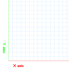
Here is a 2D Cartesian coordinate system, which should look familiar to anyone who
has ever taken a math class:

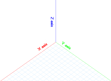
In 2D space, we have 2 dimensions in the coordinate system, X and Y. In 3D space, we need to add a 3rd dimension Z. In this project, the X and Y axes describe the ground and the Z axis describes the position above ground.

Eye Coordinates
The world coordinates represent the 3D coordinates that we are attempting to draw to the screen. In order to do this, it is first necessary to define a viewpoint, commonly referred to as the "eye". The world coordinates must then be manipulated such that the origin is at the eye, the X and Y axes are parallel to the screen, and the Z-axis points outwards perpendicular to the screen.
We must also introduce the concept of spherical coordinates -- a coordinate system where a point is described by its distance from the origin, ρ (pronounced "rho"), and its orientation given by 2 angles, θ and φ (theta and phi). This concept will be used below.
To convert screen to eye coordinates, the following steps need to be taken:
-
Move origin from the world origin (0, 0, 0) to the eye origin described by the
coordinates
 .
The distance moved is represented by ρ and we can
write
  in spherical coordinates.
- Rotate the coordinate system about the Z-axis by a predetermined amount, in this case the angle θ. This will set the location of the eye horizontally on the screen; as the value of θ is changed, picture yourself on the ground, walking around the object.
- Rotate the coordinate system about the X-axis by the angle φ. This will set the location of the eye vertically on the screen; as this value is changed, imagine yourself viewing the object in the center from different positions as you climb up and down a ladder.
We now have the points  describing the world coordinates of each point in the object (this is the independent
variable). We also have the constant point
 describing where the eye is located on the screen (in both Cartesian and spherical coordinates). We are also given the angles θ and ρ describing the two rotations necessary to place the objects on the screen viewed from whatever position we want.
The simplest way to describe these equations is via a "viewing matrix" V such that


![[Xe Ye Ze] = [xe ye ze]*V [Xe Ye Ze] = [xe ye ze]*V](/images/eqn_xe_ye_ze_xe_ye_ze_v.png)
See pages 141-146 of Ammeraal for more details. Note that each matrix corresponds to each
step in the outline above, and matrices are multiplied by each other to combine into a
single transform. Also note that ρ is obtained by using the spherical coordinate
representations of  and simplifying. This level of math is outside the
scope of this article.
Perspective
It's possible to draw the X and Y eye coordinates directly and simply ignore the Z-axis but this causes a problem: objects that are far away will look the same as objects that are nearby. In real life, the further away an object is, the smaller it looks. This is called "perspective", and can be modeled by decreasing the distance from the point to the origin based on the value of the Z.
In order to describe the perspective, we need to take into account the distance from the eye to the screen – if the eye is close to the screen, the object will be far more distorted than if it is further away. We will use the variable d for this. This value can be arbitrarily set, or it can be calculated based on the size of the object and the value of ρ outlined in the previous section.
The equations for obtaining the perspective transformation are as follows,
with  being the point on the screen
and
  being the point in eye coordinates (outlined above).


One additional thing to keep in mind is that the calculations are done with the assumption that the screen origin is in the top left corner; however, it makes more sense to start in the center of the screen. Thus the X and Y values above need to be added and subtracted from the coordinates of the center; the Y-coordinates are subtracted since the screen's Y-axis increases as it goes down, while the equations follow standard math conventions of the Y-axis values decreasing as it goes down.
Applying the equations
In order to convert a given 3D point into a 2D point, the following pseudocode is used. Assume 1-based indexing for the matrix, so V[1][1] refers to the first element.
Matrix worldToEye
	Given rho, theta, phi
	V[1][1] = -sin(theta)	V[1][2] = -cos(phi) * cos(theta)	V[1][3] = sin(phi) * cos(theta)
	V[2][1] = cos(theta)	V[2][2] = -cos(phi) * sin(theta)	V[2][3] = sin(phi) * sin(theta)
	V[3][1] = 0		V[3][2] = sin(phi)		V[3][3] =cos(phi)	V[3][4]=-rho
	Return V
End

Point2D worldToScreen(Point3D worldPoint)
	V = worldToEye
	xE = xW * V[1][1] + yW * V[2][1]
	yE = xW * V[2][1] + yW * V[2][2] * zW * V[3][2]
	zE = xW * V[3][1] + yW * V[2][3] * zW * V[3][3] + v[4][3]

	X = -d * xE / zE
	Y = -d * yE / zE

	return new Point2D(centerX + X, centerY - Y)
End
Given the above equations, we can render any 3D point to the screen. We can also draw lines and more complex shapes between those points.
Back Face Culling
In a 3D world, objects can be viewed from multiple angles; depending on the angle, different parts of the object are visible. If we are trying to render a flat square with a red front and blue back, we need to know which way the object is facing relative to the eye in order to determine what color to use to fill it.
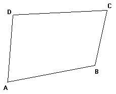
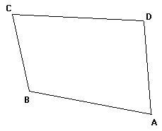
A simple technique known as back-face culling can be used here. It is based on the principle that if an object is viewed from the back, the orientation of the points defining it is reversed. Try drawing a figure like the one below on a piece of paper, then flip it over in front of your screen; you'll see what I mean.


Notice that following the sequence A, B, C, D in the first figure results in a counterclockwise motion, while following the same sequence in the second figure (which is really the first image viewed from behind) results in a clockwise motion. This will be used to our advantage.
Assume that all 3D points of a polygon face are given in such a way that when the face is viewed from the front, its points should be counterclockwise. Thus, if the points end up clockwise while rendering, we know that we are viewing that face from the back. Based on this knowledge, we know what color needs to be used to fill the polygon.
Set As = worldToScreen(A), Bs = worldToScreen(B), Cs = worldToScreen(C), Ds = worldToScreen(D)
If orientation(As, Bs, Cs, Ds) is counterclockwise
	Set color = frontColor
else
	Set color = backColor
end if
fillPolygon(As, Bs, Cs, Ds)
Rendering a 3D world
In order to give a sense of where things are, the coordinate system is often rendered on-screen. In order to do this, one simply needs to draw a line from the origin (0,0,0) to an arbitrarily large point at distance D on each of the 3 axes. In other words, lines are drawn from (0,0,0) to (D,0,0), (0,D,0), and (0,0,D). There is no official standard for coloring the axes but a common mnemonic is to use red for X, green for Y, and blue for Z – since RGB and XYZ are in the same "standard" order.
References
Ammeraal, L., and Kang Zhang. Computer Graphics for Java Programmers. 2nd ed. Chichester, England: John Wiley & Sons, 2007.
![[XML]](/images/xml.png)
Comments (1)
Leave a comment